Flow diagrams
A flow diagram shows structure: components and how they connect, dependencies, task order, states, and business rules with their branches. This guide is about drawing one well. The flow spec reference lists every field and its allowed values.
Two habits help throughout. Give every node and edge a short id of your own (client-api, not
a number), because ids keep an element the same from one version to the next. And run
diago check -strict on the spec before you render it: it reports content findings without
drawing anything.
Nodes and shapes
Section titled “Nodes and shapes”Most nodes are plain rectangles, the default. Give each other shape one role and keep it, so the reader learns the vocabulary once:
| Shape | Role | In text art |
|---|---|---|
rect |
services, processes, steps (the default) | a box |
rounded |
outside actors (users, clients, external systems); a flowchart’s start and end | rounded corners |
cylinder |
anything that holds state: a database, cache, queue, bucket | a double top border |
diamond |
decisions only | ◇ marks |
hexagon |
gateways, proxies | a box, like rect |
parallelogram |
input and output | a box, like rect |
circle |
events, start and end markers, short labels | like rounded |
{ "type": "flow", "direction": "RIGHT", "ignore": ["shape-soup"], "nodes": [ {"id": "user", "label": "User", "shape": "rounded"}, {"id": "upload", "label": "Upload", "shape": "parallelogram"}, {"id": "gateway", "label": "Gateway", "shape": "hexagon"}, {"id": "service", "label": "Service", "shape": "rect"}, {"id": "valid", "label": "Valid?", "shape": "diamond"}, {"id": "db", "label": "Database", "shape": "cylinder"}, {"id": "done", "label": "Done", "shape": "circle"} ], "edges": [ {"id": "user-upload", "from": "user", "to": "upload"}, {"id": "upload-gateway", "from": "upload", "to": "gateway"}, {"id": "gateway-service", "from": "gateway", "to": "service"}, {"id": "service-valid", "from": "service", "to": "valid"}, {"id": "valid-db", "from": "valid", "to": "db", "label": "yes"}, {"id": "db-done", "from": "db", "to": "done"} ]}

  ╭──────╮    ┌────────┐    ┌──────────┐    ┌──────────┐    ┌────────────┐    ╒══════════╕    ╭──────╮
  │ User │───►│ Upload │───►│ Gateway  │───►│ Service  │───►│ ◇ Valid? ◇ │───►│ Database │───►│ Done │
  ╰──────╯    └────────┘    └──────────┘    └──────────┘    └────────────┘    └──────────┘    ╰──────╯
                                                                          yes
This spec draws all seven shapes to show them, which is more than a real diagram should. Keep to
about 4 distinct shapes: check reports shape-soup above 5,
and the spec above silences it with "ignore": ["shape-soup"] because the finding is the
point. Text art keeps only rect, rounded, cylinder and diamond apart, as the art above
shows: when a diagram may be read as text, a role shown by hexagon, parallelogram or circle
should also be in its label.
Keep labels to 1 to 3 words and prefer role names to identifiers: “Auth Service”, not
auth-svc-v2. A word over 24 characters raises unbreakable-token, and a label over 60
characters raises long-label.
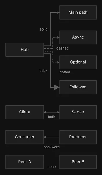
An edge is drawn solid unless you say otherwise. The line style carries meaning, and it survives in text art:
| Style | Meaning | In text art |
|---|---|---|
solid |
the main or synchronous path (the default) | ─ │ |
dashed |
async calls, responses, events | ╌ ╎ |
dotted |
optional links, monitoring, logging | ┈ ┊ |
thick |
the one path the reader should follow, at most one per diagram | ━ ┃ |
direction on an edge says where the arrowheads go: forward (the default) at the target,
backward at the source, both at both ends, none at neither. Use both for a
request and response pair, as one edge rather than two, and none for a peer link with no flow.
{ "type": "flow", "direction": "RIGHT", "nodes": [ {"id": "hub", "label": "Hub"}, {"id": "s1", "label": "Main path"}, {"id": "s2", "label": "Async"}, {"id": "s3", "label": "Optional"}, {"id": "s4", "label": "Followed"}, {"id": "c1", "label": "Client"}, {"id": "c2", "label": "Server"}, {"id": "p1", "label": "Producer"}, {"id": "p2", "label": "Consumer"}, {"id": "n1", "label": "Peer A"}, {"id": "n2", "label": "Peer B"} ], "edges": [ {"id": "hub-s1", "from": "hub", "to": "s1", "label": "solid", "style": "solid"}, {"id": "hub-s2", "from": "hub", "to": "s2", "label": "dashed", "style": "dashed"}, {"id": "hub-s3", "from": "hub", "to": "s3", "label": "dotted", "style": "dotted"}, {"id": "hub-s4", "from": "hub", "to": "s4", "label": "thick", "style": "thick"}, {"id": "c1-c2", "from": "c1", "to": "c2", "label": "both", "direction": "both"}, {"id": "p1-p2", "from": "p2", "to": "p1", "label": "backward", "direction": "backward"}, {"id": "n1-n2", "from": "n1", "to": "n2", "label": "none", "direction": "none"} ]}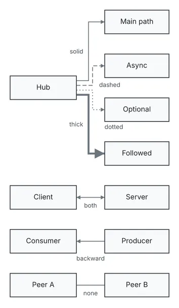
                solid ┌────────────┐
                 ┌───►│ Main path  │
                 │    └────────────┘
                 │
                 │
                 │    ┌────────────┐
  ┌──────────┐   │ ┌╌►│   Async    │
  │          │───┘ ╎  └────────────┘
  │   Hub    │╌╌╌╌╌┘ dashed
  │          │┈┈┈┈┈┐ dotted
  │          │━━━┐ ┊  ┌────────────┐
  └──────────┘   ┃ └┈►│  Optional  │
                 ┃    └────────────┘
                 ┃
                 ┃
                 ┃    ┌────────────┐
                 └━━━►│  Followed  │
                thick └────────────┘


  ┌──────────┐        ┌────────────┐
  │  Client  │◄──────►│   Server   │
  └──────────┘  both  └────────────┘


  ┌──────────┐        ┌────────────┐
  │ Consumer │◄───────│  Producer  │
  └──────────┘        └────────────┘
              backward

  ┌──────────┐        ┌────────────┐
  │  Peer A  │────────│   Peer B   │
  └──────────┘  none  └────────────┘
Edge ids matter more than they look. diago diff and render -previous use them to decide which
edge is which across two versions, so an edge you relabel is reported as changed, not as one
removed and one added. Without an id diago derives from->to#n, which breaks when you rename
a node.
Label an edge with a verb phrase (publishes order, not data) and only where its two ends do
not already make the meaning obvious: each label is one more thing to place, so fewer labels
read cleaner. A label such as data or calls is reported as
vague-edge-label.
Direction
Section titled “Direction”direction is the way the diagram flows: DOWN, UP, RIGHT, LEFT or AUTO. Pick it by
the medium’s tight axis, not by habit. A terminal is short of width, so a long chain belongs
DOWN; a slide or a document is short of height, so the same chain belongs RIGHT, as a banner.
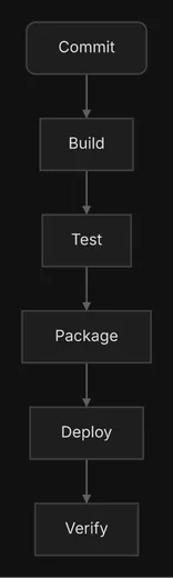
Here is one six-step chain both ways, as text art:
{ "type": "flow", "direction": "DOWN", "nodes": [ {"id": "commit", "label": "Commit", "shape": "rounded"}, {"id": "build", "label": "Build"}, {"id": "test", "label": "Test"}, {"id": "package", "label": "Package"}, {"id": "deploy", "label": "Deploy"}, {"id": "verify", "label": "Verify"} ], "edges": [ {"id": "commit-build", "from": "commit", "to": "build"}, {"id": "build-test", "from": "build", "to": "test"}, {"id": "test-package", "from": "test", "to": "package"}, {"id": "package-deploy", "from": "package", "to": "deploy"}, {"id": "deploy-verify", "from": "deploy", "to": "verify"} ]}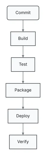
   ╭────────╮
   │ Commit │
   ╰────────╯
        │
        │
        ▼
   ┌────────┐
   │ Build  │
   └────────┘
        │
        │
        ▼
    ┌──────┐
    │ Test │
    └──────┘
        │
        │
        ▼
  ┌──────────┐
  │ Package  │
  └──────────┘
        │
        │
        ▼
   ┌────────┐
   │ Deploy │
   └────────┘
        │
        │
        ▼
   ┌────────┐
   │ Verify │
   └────────┘
{ "type": "flow", "direction": "RIGHT", "nodes": [ {"id": "commit", "label": "Commit", "shape": "rounded"}, {"id": "build", "label": "Build"}, {"id": "test", "label": "Test"}, {"id": "package", "label": "Package"}, {"id": "deploy", "label": "Deploy"}, {"id": "verify", "label": "Verify"} ], "edges": [ {"id": "commit-build", "from": "commit", "to": "build"}, {"id": "build-test", "from": "build", "to": "test"}, {"id": "test-package", "from": "test", "to": "package"}, {"id": "package-deploy", "from": "package", "to": "deploy"}, {"id": "deploy-verify", "from": "deploy", "to": "verify"} ]}

  ╭────────╮    ┌────────┐    ┌──────┐    ┌──────────┐    ┌────────┐    ┌────────┐
  │ Commit │───►│ Build  │───►│ Test │───►│ Package  │───►│ Deploy │───►│ Verify │
  ╰────────╯    └────────┘    └──────┘    └──────────┘    └────────┘    └────────┘
In text art the DOWN chain is 14 columns wide and 33 lines tall; the RIGHT chain is 82
columns wide and 3 lines tall. The reverse holds for a wide fan-out, one node with many children:
RIGHT keeps it narrow in a terminal, and DOWN suits an image. A hierarchy, a decision tree or
layers read best DOWN.
Set direction yourself rather than rely on AUTO, which chooses from the shape of the graph
and does not know where the diagram will be read. UP fits only when the reader expects
foundations at the bottom, and LEFT almost never. When in doubt, render both and keep the one
that fits and reads better.
Groups
Section titled “Groups”A group draws a frame around the nodes it contains. Use one for a boundary that matters to the
reader: a deployment boundary, a package, a team, a trust zone. A group of one member only
adds a frame, so give it at least 2. A group id in another group’s contains nests it, up to 3 levels; a fourth is a validation
error.
{ "type": "flow", "title": "Production", "direction": "DOWN", "nodes": [ {"id": "client", "label": "Client", "shape": "rounded"}, {"id": "api", "label": "API"}, {"id": "auth", "label": "Auth"}, {"id": "db", "label": "Database", "shape": "cylinder"} ], "edges": [ {"id": "client-api", "from": "client", "to": "api", "label": "sends request"}, {"id": "api-auth", "from": "api", "to": "auth", "label": "verifies"}, {"id": "api-db", "from": "api", "to": "db", "label": "reads orders"} ], "groups": [ {"id": "cloud", "label": "Cloud", "color": "blue", "contains": ["services", "db"]}, {"id": "services", "label": "Services", "contains": ["api", "auth"]} ]}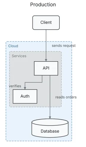
            Production

               ╭────────╮
               │ Client │
               ╰────────╯
                    │
                    │ sends request
                    │
  ┌─ Cloud ─────────┼────────┐
  │                 │        │
  │  ┌─ Services ───┼─────┐  │
  │  │              ▼     │  │
  │  │          ┌──────┐  │  │
  │  │          │ API  │  │  │
  │  │          └──────┘  │  │
  │  │   verifies │  │    │  │
  │  │            │  │    │  │
  │  │      ┌─────┘  │    │  │
  │  │      ▼        │    │  │
  │  │  ┌──────┐     │    │  │
  │  │  │ Auth │     │    │  │
  │  │  └──────┘     │    │  │
  │  └───────────────┼────┘  │
  │                  │       │
  │     reads orders │       │
  │                  ▼       │
  │            ╒══════════╕  │
  │            │ Database │  │
  │            └──────────┘  │
  └──────────────────────────┘
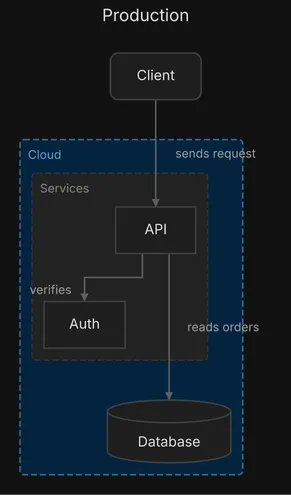
Groups are where color pays off best: to tell domains apart, color the groups (here Cloud),
not their nodes. Deeper groups get progressively different fill shading, so nesting reads at a
glance. In text art, keep a group label to one short word: a long one widens the frame, and the
art with it. The title above the diagram is covered below.
Decisions
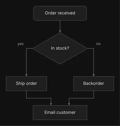
Section titled “Decisions”A diamond is for a decision, and every exit needs a label. A diamond with two or more exits
and one unlabeled raises unlabeled-branch. Branches that
rejoin simply point to the same node.
{ "type": "flow", "direction": "DOWN", "nodes": [ {"id": "start", "label": "Order received", "shape": "rounded"}, {"id": "stock", "label": "In stock?", "shape": "diamond"}, {"id": "ship", "label": "Ship order"}, {"id": "backorder", "label": "Backorder"}, {"id": "notify", "label": "Email customer"} ], "edges": [ {"id": "start-stock", "from": "start", "to": "stock"}, {"id": "stock-ship", "from": "stock", "to": "ship", "label": "yes"}, {"id": "stock-backorder", "from": "stock", "to": "backorder", "label": "no"}, {"id": "ship-notify", "from": "ship", "to": "notify"}, {"id": "backorder-notify", "from": "backorder", "to": "notify"} ]}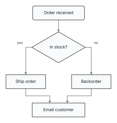
          ╭────────────────╮
          │ Order received │
          ╰────────────────╯
                   │
                   │
                   ▼
          ┌────────────────┐
          │ ◇ In stock? ◇  │
          └────────────────┘
               │ yes  │ no
               │      │
         ┌─────┘      └─────┐
         ▼                  ▼
  ┌────────────┐     ┌────────────┐
  │ Ship order │     │ Backorder  │
  └────────────┘     └────────────┘
         │                  │
         │                  │
         └─────┐      ┌─────┘
               ▼      ▼
          ┌────────────────┐
          │ Email customer │
          └────────────────┘
Flat edges
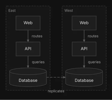
Section titled “Flat edges”An ordinary edge says “this comes before that”, so diago ranks its ends. A link between peers
has no order: replication between two sites that each serve their own traffic, or a sync
between two services at one level. Mark it "flat": true and diago leaves the ends where the
rest of the diagram puts them, side by side when there is room, then routes the edge on the
finished layout. Without it the two sites below would stack.
{ "type": "flow", "direction": "DOWN", "nodes": [ {"id": "east_web", "label": "Web"}, {"id": "east_api", "label": "API"}, {"id": "east_db", "label": "Database", "shape": "cylinder"}, {"id": "west_web", "label": "Web"}, {"id": "west_api", "label": "API"}, {"id": "west_db", "label": "Database", "shape": "cylinder"} ], "edges": [ {"id": "east-web-api", "from": "east_web", "to": "east_api", "label": "routes"}, {"id": "east-api-db", "from": "east_api", "to": "east_db", "label": "queries"}, {"id": "west-web-api", "from": "west_web", "to": "west_api", "label": "routes"}, {"id": "west-api-db", "from": "west_api", "to": "west_db", "label": "queries"}, { "id": "east-west", "from": "east_db", "to": "west_db", "label": "replicates", "style": "dashed", "flat": true } ], "groups": [ {"id": "east", "label": "East", "contains": ["east_web", "east_api", "east_db"]}, {"id": "west", "label": "West", "contains": ["west_web", "west_api", "west_db"]} ]}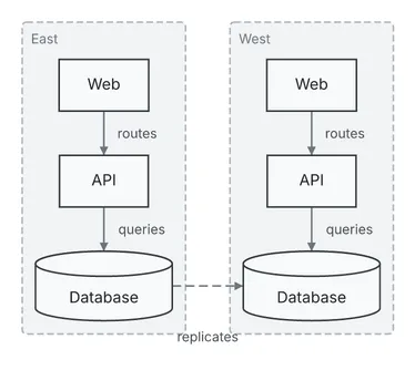
  ┌─ East ─────────┐     ┌─ West ─────────┐
  │                │     │                │
  │    ┌──────┐    │     │    ┌──────┐    │
  │    │ Web  │    │     │    │ Web  │    │
  │    └──────┘    │     │    └──────┘    │
  │        │       │     │        │       │
  │ routes │       │     │ routes │       │
  │        ▼       │     │        ▼       │
  │    ┌──────┐    │     │    ┌──────┐    │
  │    │ API  │    │     │    │ API  │    │
  │    └──────┘    │     │    └──────┘    │
  │        │       │     │        │       │
  │        │ queries     │        │ queries
  │        ▼     replicates       ▼       │
  │  ╒══════════╕  │     │  ╒══════════╕  │
  │  │ Database │╌╌┼╌╌╌╌╌┼╌►│ Database │  │
  │  └──────────┘  │     │  └──────────┘  │
  └────────────────┘     └────────────────┘
Two rules keep a flat edge honest. A node whose only edges are flat is placed as an unconnected
node, wherever there is room, not beside its partner, so keep one ordinary link on it: a standby
database with nothing else attached keeps its replication edge from the primary ordinary, which
puts it under the primary. And do not mark a link flat when it is part of the flow, such as a
request, a dependency or a pipeline step; a flat edge cannot be a self-loop. When no clean route
exists, the edge is laid out as an ordinary one and the render warns with
flat-edge-ranked.
Color is the weakest channel, since text art drops it: never let it carry meaning alone.
- Use 0 to 2 accents per diagram: one for the focus (the entry point, the component under
discussion),
orangefor a problem. Leave the rest uncolored. - Say what a color means in the sentence above the diagram. A flow diagram has no color legend.
- Color groups rather than the nodes inside them to tell domains apart.
- Avoid
green,blueandredin a spec you will diff: the diff draws added elements green, changed ones blue and removed ones red.
Values are red, green, blue, yellow, orange, purple, gray or #rrggbb, on nodes,
edges and groups.
Add a top-level "title" when the diagram stands alone in a file. It is a band above the
diagram in SVG and PNG and a centered first line in text art, as in the Production diagram
above. It never affects the layout.
Aim for 3 to 12 nodes in a chat reply and 5 to 15 in a document. check reports too-large
above 20 nodes (groups do not count). Past that, split the subject into an overview and one
zoom-in per area, and say how they fit together.
For every field and value, see the flow spec reference.